
Five ways to condense a vapor and keep a process running
A working reference on condensers and heat exchangers used across distillation, solvent recovery, and reflux systems — what each type does, where it fits, and when to choose it over the rest.
Built to condense vapors that ordinary HVAC equipment can't touch
A chemical condenser is a heat exchanger used in chemical processes to condense vapors into liquid form by removing heat — common across distillation, solvent recovery, reflux systems, and chemical reactors. Unlike HVAC condensers, it's engineered for corrosive vapors, toxic gases, high temperatures, active chemical reactions, and condensable solvents.
Working principle
Five types in use
Shell and Tube Condenser
- The most common configuration in chemical plants
- Vapor flows through the shell or the tubes
- Cooling water runs in the opposite direction
Surface Condenser
- No direct contact between vapor and the cooling medium
- Used specifically for pure product recovery
Air-Cooled Condenser
- Uses ambient air rather than water
- No cooling water supply required
- Suited to sites where water is limited
Direct Contact Condenser
- Cooling liquid contacts the vapor directly
- Delivers high heat transfer efficiency
- Common in scrubbing systems
Reflux Condenser
- Sits on top of a distillation column
- Returns part of the condensed liquid back to the column
- Improves overall separation efficiency
Materials of construction
Chemical condensers have to resist corrosion, so material selection is driven by chemical compatibility with the process fluid.
Design parameters
Applications
Common issues
Chemical condenser vs. HVAC condenser
| Feature | Chemical Condenser | HVAC Condenser |
|---|---|---|
| Purpose | Process vapor condensation | Refrigerant condensation |
| Materials | Corrosion resistant | Standard copper / aluminum |
| Design pressure | Often high | Moderate |
| Fluid type | Chemicals / solvents | Refrigerant |
Interested in Chemical Condenser?
Contact our team for specifications, pricing, and availability.
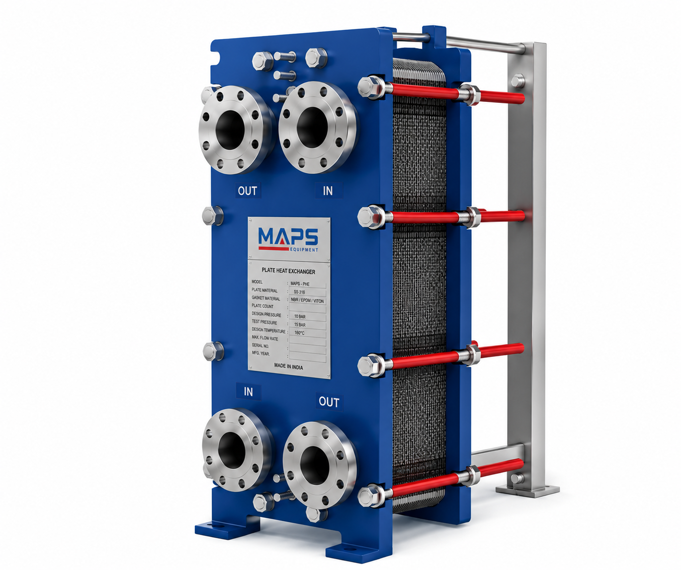
Corrugated plates, alternate channels, a footprint that fits almost anywhere
A PHE is a compact heat exchanger that uses corrugated metal plates to transfer heat between two fluids, widely used across HVAC, chemical, food, and pharmaceutical industries for its high heat transfer efficiency and small footprint.
Working principle
The corrugated plate pattern creates turbulence, which is what drives the higher heat transfer coefficient compared with smooth-tube designs.
Main components
Four types of plate heat exchangers
Gasketed PHE
- Plates sealed with rubber gaskets
- Can be opened fully for cleaning
- Suited to moderate pressure and temperature
Brazed Plate Heat Exchanger (BPHE)
- Plates brazed together, usually with copper
- Compact and fully sealed, no gaskets
- Used in chillers and refrigeration systems
Welded Plate Heat Exchanger
- Plates welded together
- Suited to aggressive or high-temperature fluids
- No gaskets present in the flow area
Semi-Welded PHE
- Combines welded and gasketed construction
- Common choice for ammonia and other refrigerants
Advantages
- Very high heat transfer efficiency
- Compact size, less floor space needed
- Low refrigerant or fluid charge
- Easy capacity expansion by adding plates
- Easy cleaning in gasketed designs
Disadvantages
- Gasket failure risk in gasketed types
- Not ideal for very dirty fluids
- Pressure drop can run high
- Limited to moderate pressure in gasketed types
Applications
PHE vs. shell & tube
| Feature | PHE | Shell & Tube |
|---|---|---|
| Heat transfer efficiency | Very high | Moderate |
| Size | Compact | Large |
| Cleaning | Easy (gasketed) | Difficult |
| High pressure | Limited (gasketed) | Excellent |
| Fouling tolerance | Low | Better |
Design parameters
Interested in PHE?
Contact our team for specifications, pricing, and availability.
A tube bundle inside a shell — the workhorse of process heat transfer
One of the most widely used heat exchanger types across industry: a bundle of tubes enclosed inside a cylindrical shell, with one fluid running through the tubes and the other flowing outside them, inside the shell. Common in oil & gas, chemical plants, power plants, refineries, and HVAC.
Construction
Shell
The cylindrical outer body that contains the tube bundle.
Tube bundle
The group of tubes running inside the shell.
Tube sheets
Hold the tubes in place at each end.
Baffles
Direct shell-side fluid flow and improve heat transfer.
Inlet & outlet nozzles
Provide fluid entry and exit points.
Channel head
Distributes the tube-side fluid into the bundle.
Working principle
One fluid flows inside the tubes — the tube-side fluid. The other flows inside the shell, around the tubes — the shell-side fluid. Heat transfers through the tube wall, and the two fluids never mix. Most designs run in counterflow for better heat transfer.
Three configurations
Fixed Tube Sheet Type
- Tubes fixed at both ends
- Simple and economical to build
- Difficult to clean on the shell side
U-Tube Type
- Tubes bent into a U-shape
- Only one tube sheet required
- Handles thermal expansion well
Floating Head Type
- One tube sheet fixed, the other floats
- Allows for thermal expansion
- Easy to clean
Flow arrangements
Advantages
- Handles high pressure and temperature
- Suited to large heat duties
- Strong and durable construction
- Can handle dirty fluids
- Wide range of materials available
Disadvantages
- Large physical size
- Heavy compared with alternatives
- Lower heat transfer coefficient than PHE
- Higher maintenance cost
Applications
Shell & tube vs. plate heat exchanger
| Feature | Shell & Tube | Plate Heat Exchanger |
|---|---|---|
| Pressure handling | Very high | Moderate |
| Temperature handling | Very high | Moderate |
| Size | Large | Compact |
| Cleaning | Moderate | Easy (gasketed) |
| Fouling resistance | Better | Lower |
When to choose shell & tube
- High pressure or high temperature is involved
- Fluids are dirty or viscous
- A large heat duty is required
- Thermal expansion needs to be managed
Interested in Shell & Tube Heat Exchanger?
Contact our team for specifications, pricing, and availability.
Two channels, wound into a spiral, built to shrug off fouling
A spiral condenser rolls two metal plates into a spiral form, creating two separate flow channels. It's a special case of the spiral heat exchanger, purpose-built for condensation duty — and a strong choice when the vapor stream is fouling or viscous.
Construction
Two long metal plates wind around a central core, forming two spiral channels: one for the vapor being condensed, one for the cooling medium — water or brine. The channels are fully welded and sealed at the edges, with end covers providing the inlet and outlet connections. The single-channel flow design is what keeps fouling down.
Working principle
The spiral geometry promotes high turbulence, uniform heat transfer, and a self-cleaning effect along the channel walls.
Advantages
- Excellent for fouling fluids
- High heat transfer coefficient
- Compact footprint
- Suited to corrosive media with the right material
- Low pressure drop
Disadvantages
- Limited to moderate pressure
- Not suited to extremely high temperatures
- More expensive than shell & tube for small duties
Applications
Spiral vs. shell & tube condenser
| Feature | Spiral Condenser | Shell & Tube |
|---|---|---|
| Fouling resistance | High | Moderate |
| Size | Compact | Larger |
| Cleaning | Easier (single channel) | More complex |
| Pressure handling | Moderate | High |
| Efficiency | High | Moderate |
Materials of construction
When to choose a spiral condenser
- Vapor contains solids or fouling components
- Available space is limited
- Operating pressure is moderate
- High efficiency is a priority
- Frequent cleaning is expected
Interested in Spiral Condenser?
Contact our team for specifications, pricing, and availability.
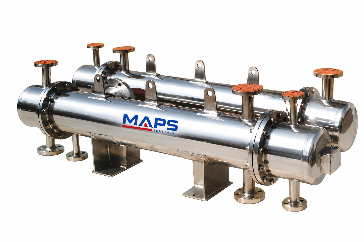
A standard shell & tube exchanger, with a separator standing guard ahead of it
This is a conventional shell and tube exchanger built to handle vapor-liquid mixtures. The catchpot — also called a separator or knockout pot — collects condensed liquid or removes entrained droplets before the fluid enters the shell or leaves it. The arrangement is common across chemical, petrochemical, and refrigeration applications.
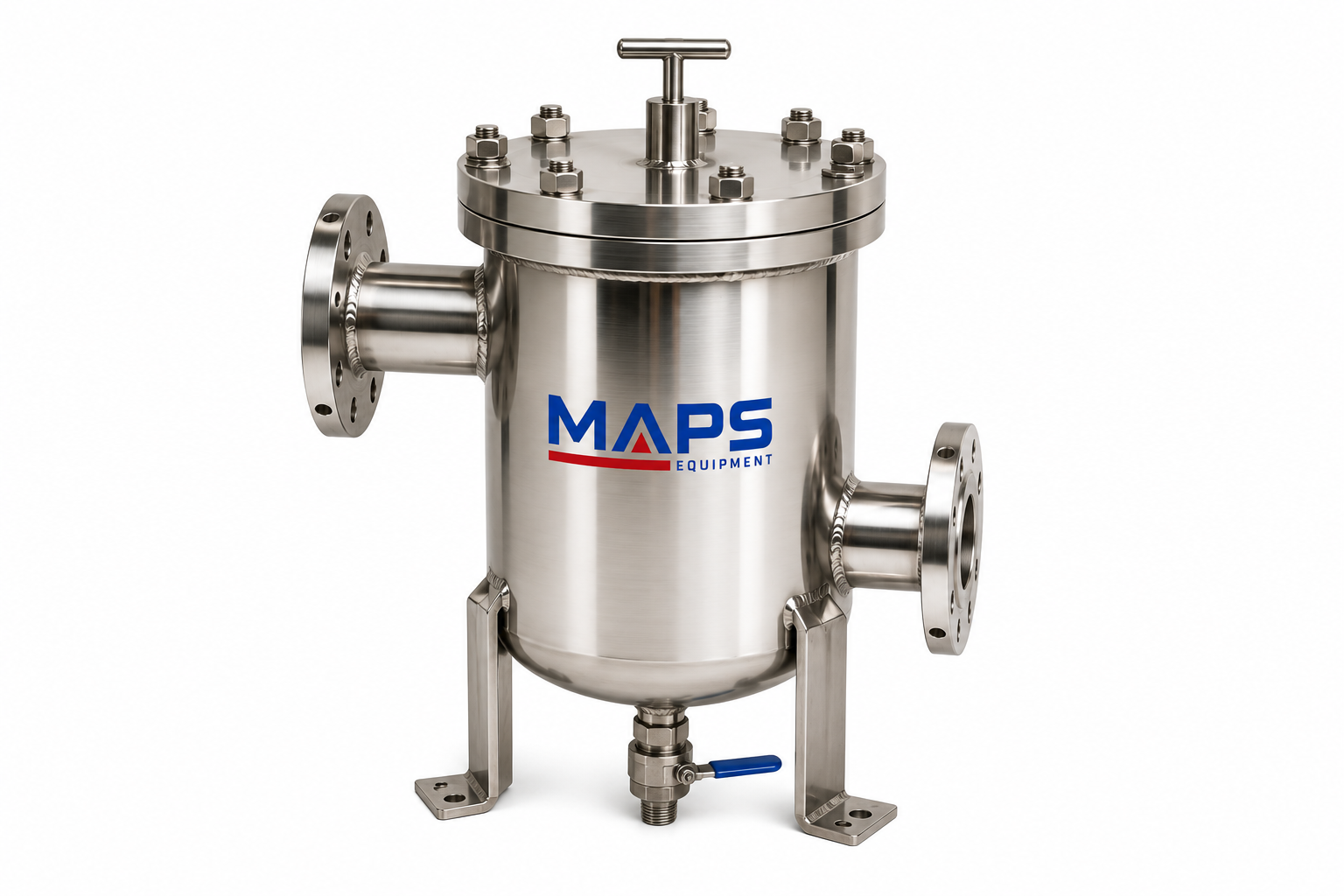
What the catchpot is for
Liquid separation
Removes condensate from vapor streams before it reaches the heat exchanger.
Equipment protection
Prevents damage to pumps, valves, or compressors caused by liquid carryover.
Maintained efficiency
Reduces pressure drop and keeps heat transfer steady by avoiding two-phase flow inside the exchanger.
Working principle
In effect, the catchpot ensures the heat exchanger only ever sees a single-phase fluid, which is what protects both performance and equipment.
Typical applications
Advantages
- Protects downstream equipment from liquid slugging
- Reduces fouling and erosion in the heat exchanger
- Maintains heat transfer efficiency
- Handles vapor-liquid mixtures efficiently
- Simple addition to an existing shell & tube design
Disadvantages
- Requires additional space
- Minor increase in pressure drop
- Needs regular drainage of collected liquid
Design considerations
With catchpot vs. conventional shell & tube
| Feature | With Catchpot | Conventional STHE |
|---|---|---|
| Handles two-phase flow | Yes | No — single-phase only |
| Fouling | Lower | Higher if condensate present |
| Equipment protection | High | Moderate |
| Space requirement | Slightly more | Standard |
| Maintenance | Minor extra | Standard |
Interested in Shell & Tube + Catchpot?
Contact our team for specifications, pricing, and availability.
Five exchangers, five different jobs — pick by what the fluid is doing
A short summary to keep nearby when the spec sheet needs a fast decision.
Chemical Condenser
For condensing corrosive, toxic, or high-temperature process vapors.
Plate Heat Exchanger
For compact, high-efficiency duties at moderate pressure.
Shell & Tube
For high pressure, high temperature, and large heat duties.
Spiral Condenser
For fouling or viscous fluids in a tight footprint.